10. Observation 구현
- date
- 2월 26, 2026
- status
- Public
- tags
- unrealRL
1. 소개#
이전 단계에서는 BP_SpiderTrainingManager에서 BP_SpiderInteractor를 생성하고, 이를 BP_SpiderLearningManager에 Listener로 등록한 뒤, BP_SpiderRobot을 Agent로 등록하는 구조까지 구성했다.
또한, 학습기가 출력한 24개의 Continuous Action 값을 BP_SpiderInteractor에서 읽고, SpiderJointControllerComponent.ApplyJointActions로 전달하여 24개 Physics Constraint의 목표 회전을 갱신하는 구조도 구현했다.
따라서, 지금까지는 학습기가 Action을 출력했을 때 그 Action을 로봇 관절에 전달하는 통로를 만든 상태라고 볼 수 있다.
이번 단계에서는 반대로, 로봇의 현재 상태를 학습기가 읽을 수 있도록 Observation 구조를 구현해보자
2. 작업 전#
구현할 내용을 정리해보면 결국은,
BP_SpiderInteractor안에서 Observation 입력 통로를 만드는 작업이다.이미 Action 쪽은 이렇게 되어 있었다
flowchart LR
    A[Policy] --> B[Action 24개]
    B --> C[BP_SpiderInteractor.Perform Agent Action]
    C --> D[Get Continuous Action]
    D --> E[SpiderJointControllerComponent.ApplyJointActions]
    E --> F[24개 Physics Constraint 목표 회전 갱신]
이번에는 반대로 이 흐름을 만들어 내면 된다.
flowchart LR
    A[BP_SpiderRobot 현재 물리 상태] --> B[BP_SpiderInteractor.Gather Agent Observation]
    B --> C[Observation Vector]
    C --> D[Policy]
    D --> E[Action 24개]
    E --> F[Perform Agent Action]
거미 로봇 학습에 필요한 상태 정보를 정의하고,
BP_SpiderInteractor에서 Observation 구조를 설계한 뒤, Policy가 사용할 입력 데이터 형태를 준비하는 것이 목표다.2.1. 구현 순서 정리#
- 구현 순서를 정리해 보면
flowchart TD
    A[1. BP_SpiderRobot에 상태값 반환 함수 만들기] --> B[2. SpiderJointControllerComponent에 관절 상태 반환 함수 만들기]
    B --> C[3. BP_SpiderInteractor에서 Observation 채우기]
인데, 핵심은
BP_SpiderInteractor가 모든 값을 직접 계산하려고 하지 말고,- 로봇 상태는
BP_SpiderRobot에서, - 관절 상태는
SpiderJointControllerComponent에서 가져오게 만들어서 추후에 만약 다리 구조가 변경되더라도 구조를 덜 무너트리게 하는 것이다.
3. [BP] BP_SpiderRobot 에 함수 생성#
3.1. GetBodyObservationValues함수 생성 및 수정#
1. 함수 생성#
우선적으로 몸체 상태 Observation 값을 반환하는 함수를 만들어야 한다
반환값은 물리값에 맞게 해당 데이터를 받도록 조정하자
Pitch
Roll
Yaw
Height
ForwardVelocity
RightVelocity
AngularVelocityX
AngularVelocityY
AngularVelocityZ
즉, Body 쪽에서 총 8개를 입력 받아야 한다
flowchart LR
    A[BP_SpiderRobot] --> B[Get Actor Rotation]
    A --> C[Get Actor Location]
    A --> D[Get Velocity]
    A --> E[Get Angular Velocity]
    B --> F[Pitch / Roll / Yaw]
    C --> G[Height]
    D --> H[Forward / Right Velocity]
    E --> I[Angular Velocity XYZ]
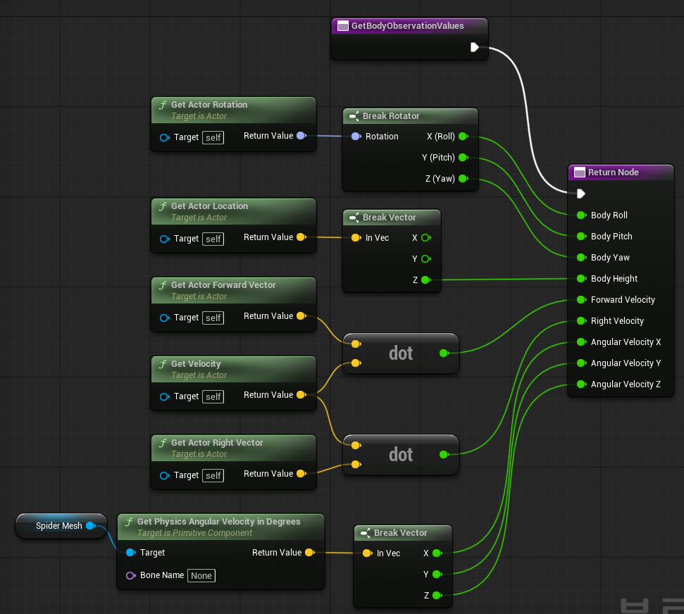
완성된 블루프린트에서의 모습
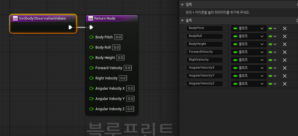
이제 이 8개 출력값에 실제 로봇 상태를 연결 해보도록 하자
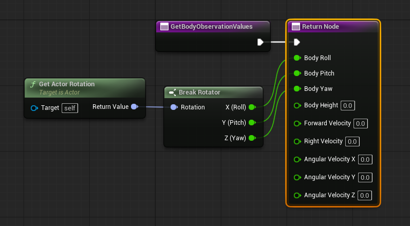
2. BodyPitch / BodyRollv / BodyYaw 연결#
그래프 빈 공간에서 우클릭해서 노드 추가(Get Actor Rotation)
그 다음
Get Actor Rotation의 Return Value에서 드래그해서(Break Rotator) 를 생성각 항목을 연결
3. Body Height 연결#
빈 공간 우클릭해서 노드 추가(Get Actor Location) → 그 다음
Return Value파란 핀에서 드래그해서(Break Vector) 추가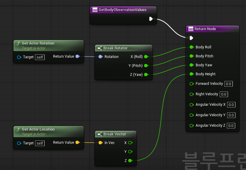
4. Forward Velocity 연결#
- 빈 공간에서 우클릭 → 노드 생성(Get Velocity), 그리고 벡터 출력 노드 추가(Get Actor Forward Vector)
Get Velocity의 Return Value에서 드래그해서 검색(Dot Product) 후 노드 생성
Dot Product란?
Dot Product는 한국어로 내적.- 즉,속도 벡터가 어떤 방향으로 얼마나 향하고 있는지 계산하는 노드
- 현재
Get Velocity는 로봇의 속도를 가져오지만, 이 값은 월드 기준 속도
예를 들면,
월드 X 방향으로 120
월드 Y 방향으로 30
월드 Z 방향으로 0
하지만 우리가 알고 싶은 건 로봇의 기준에서의 값이기 때문에,
로봇 기준 앞으로 얼마나 가는가?
로봇 기준 오른쪽으로 얼마나 밀리는가?
Dot Product를 사용
연결 구조
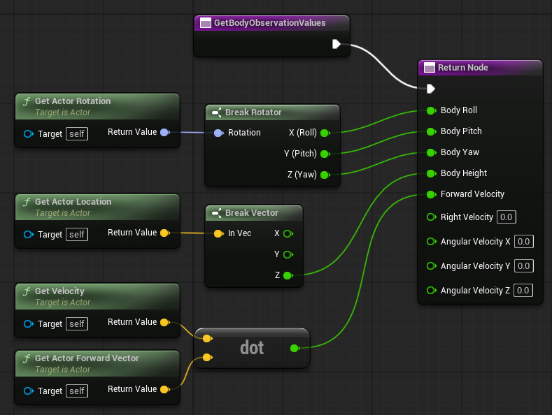
5. Right Velocity 연결#
빈 공간 우클릭해서 검색(Get Actor Right Vector) 후 노드 추가
벡터 return 쪽에 Dot Product 추가
연결
Get Velocity Return Value
→ 새 Dot Product 입력 1

Get Actor Right Vector Return Value
→ 새 Dot Product 입력 2

새 Dot Product 결과
→ Return Node의 Right Velocity
연결 구조
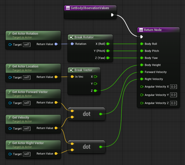
Get Velocity ─────────────┬→ Dot Product 1 → Forward Velocity
Get Actor Forward Vector ─┘

Get Velocity ─────────────┬→ Dot Product 2 → Right Velocity
Get Actor Right Vector ───┘
Forward Velocity는 앞으로 가는 속도,Right Velocity는 옆으로 미끄러지는 속도
를 구성한다.
6. Angular Velocity 3개 연결#
이 값은 몸체가 얼마나 회전하거나 흔들리는지를 알려주는 값이다. 예를 들어 로봇이 넘어지려고 회전 중인지, 바닥에서 심하게 구르고 있는지 판단하는데 쓰인다.
하지만, 이걸 적용하기 전에 어떤 컴포넌트가 물리 몸체인지를 확인해야 한다. 즉, 실제 물리 시뮬레이션이 켜져 있는 Mesh Component에서 가져와야 한다는 뜻이다.
빈 공간에서 우클릭하고 검색(Get Physics Angular Velocity in Degrees)
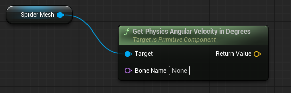
Spider Mesh가 실제 물리 시뮬레이션을 담당하는 컴포넌트인 것을 확인할 수 있다Get Physics Angular Velocity in Degrees의 노란색Return Value핀에서 드래그해서 검색Break Vector그 다음 이렇게 연결
Break Vector X → Return Node의 Angular Velocity X
Break Vector Y → Return Node의 Angular Velocity Y
Break Vector Z → Return Node의 Angular Velocity Z
완성 구조
flowchart LR
    A[Spider Mesh] --> B[Get Physics Angular Velocity in Degrees]
    B --> C[Break Vector]
    C -->|X| D[Angular Velocity X]
    C -->|Y| E[Angular Velocity Y]
    C -->|Z| F[Angular Velocity Z]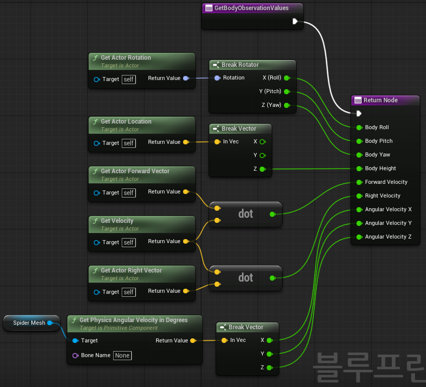
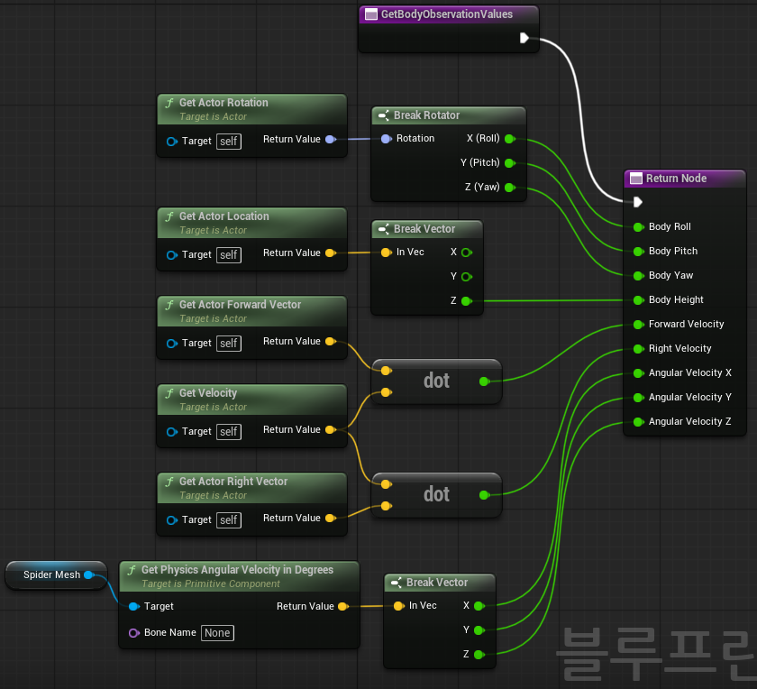
최종 구조
3.2. 관절 상태 Observation 함수 생성#
JointAngles는 24개 관절의 현재 상태를 나타내고,JointAngularVelocities는 24개 관절의 각속도 상태를 나타낸다.- 초기 구현에서는 Physics Constraint의 실제 현재각을 직접 읽기보다,
ApplyJointActions에서 마지막으로 적용한 정규화 Action 값을LastJointTargetAngles에 저장한 뒤 이를 관절 상태 Observation으로 사용한다. - 즉, 현재 단계의 목적은 실제 관절 센서를 완벽하게 구현하는 것이 아니라,
BP_SpiderInteractor가 관절 상태 배열을 읽어 Observation Vector에 포함할 수 있는 구조를 먼저 만드는 것이다.
1. SpiderJointControllerComponent.h 수정#
- 내부 코드에서
UFUNCTION(BlueprintPure, Category = "Spider Joint")
int32 GetControlledJointCount() const;
바로 아래에 아래 함수 추가
// Observation에서 사용할 관절 상태 값을 반환한다.
//
// 초기 구현에서는 실제 Physics Constraint의 현재 상대각을 직접 읽지 않고,
// ApplyJointActions에서 마지막으로 적용한 정규화 Action 값을 관절 목표 상태로 사용한다.
//
// JointAngles[i]와 JointAngularVelocities[i]는
// ActiveJointConfigs[i] / ResolvedConstraints[i]와 같은 순서를 따른다.
UFUNCTION(BlueprintPure, Category = "Spider Joint")
void GetJointObservationValues(
	TArray<float>& JointAngles,
	TArray<float>& JointAngularVelocities
) const;- 아래쪽
private:영역에서 이 부분을 찾아서
// ActiveJointConfigs와 같은 순서로 매칭되는 실제 Constraint 포인터 배열이다.
// Action[i]는 ResolvedConstraints[i]에 적용된다.
TArray<FConstraintInstance*>ResolvedConstraints;
그 아래에 이 변수 2개를 추가
// Observation용으로 마지막에 적용한 관절 목표값을 저장한다.
// 현재는 실제 관절 각도가 아니라, -1.0 ~ +1.0으로 Clamp된 ActionValue를 저장한다.
UPROPERTY()
TArray<float>LastJointTargetAngles;

// Observation용 관절 각속도 값이다.
// 1차 구현에서는 0으로 유지하고, 이후 실제 관절 각속도 계산으로 확장한다.
UPROPERTY()
TArray<float>LastJointAngularVelocities;
2. SpiderJointControllerComponent.cpp 수정#
- InitializeControlledConstraints 수정
void USpiderJointControllerComponent::InitializeControlledConstraints()
{
ResolvedConstraints.Reset();
bLoggedActionCountMismatch =false;
여기에 배열 초기화를 추가
void USpiderJointControllerComponent::InitializeControlledConstraints()
{
ResolvedConstraints.Reset();
LastJointTargetAngles.Reset();
LastJointAngularVelocities.Reset();

bLoggedActionCountMismatch =false;- 그다음
ActiveJointConfigs가 비어 있는지 검사한 뒤, 즉 이 코드 다음에:
if (ActiveJointConfigs==nullptr||ActiveJointConfigs->Num()==0)
{
UE_LOG(
LogTemp,
Warning,
TEXT("[SpiderJointController] 관절 설정이 비어 있습니다. JointConfigData 또는 JointConfigs를 설정해야 합니다.")
	);
return;
}
바로 아래에 추가
LastJointTargetAngles.Init(0.0f,ActiveJointConfigs->Num());
LastJointAngularVelocities.Init(0.0f,ActiveJointConfigs->Num());
이렇게 하면 관절 설정이 24개면 배열도 자동으로 24개가 돼. 숫자 24를 코드에 직접 박지 않아도 됨
ApplyJointActions()에 저장 코드 추가
ApplyJointActions()안에서 이 줄을 찾아서
constfloatActionValue = FMath::Clamp(JointActions[Index],-1.0f,1.0f);바로 아래에 추가
if (LastJointTargetAngles.IsValidIndex(Index))
{
LastJointTargetAngles[Index] =ActionValue;
}.cpp맨 아래에 함수 구현 추가
GetControlledJointCount()함수 아래에 이 함수를 추가
void USpiderJointControllerComponent::GetJointObservationValues(
TArray<float>&JointAngles,
TArray<float>&JointAngularVelocities
)const
{
constTArray<FSpiderJointMotorConfig>*ActiveJointConfigs =GetActiveJointConfigs();

constint32ExpectedJointCount =ActiveJointConfigs!=nullptr
		?ActiveJointConfigs->Num()
		:0;

JointAngles.Reset(ExpectedJointCount);
JointAngularVelocities.Reset(ExpectedJointCount);

if (ExpectedJointCount<=0)
	{
return;
	}

for (int32Index =0;Index<ExpectedJointCount;++Index)
	{
constfloatJointAngleValue =LastJointTargetAngles.IsValidIndex(Index)
			?LastJointTargetAngles[Index]
			:0.0f;

constfloatJointAngularVelocityValue =LastJointAngularVelocities.IsValidIndex(Index)
			?LastJointAngularVelocities[Index]
			:0.0f;

JointAngles.Add(JointAngleValue);
JointAngularVelocities.Add(JointAngularVelocityValue);
	}
}
3. 최종 구조#
flowchart TD
    A[ApplyJointActions] --> B[ActionValue 계산]
    B --> C[LastJointTargetAngles 저장]
    B --> D[Constraint 목표 회전 적용]

    E[GetJointObservationValues] --> F[LastJointTargetAngles 읽기]
    E --> G[LastJointAngularVelocities 읽기]
    F --> H[JointAngles 반환]
    G --> I[JointAngularVelocities 반환]
4. [BP] BP_SpiderInteractor 작업#
작업하기에 앞서#
이제
BP_SpiderInteractor에서 아래 세 종류 값을 모을 것이다.1. Body Observation 9개 2. Joint Angles 배열 3. Joint Angular Velocities 배열그 후, 여기에
Target Direction2개를 추가하면 전체 Observation이 완성이 된다.BP_SpiderInteractor를 열면 노드가 깨진 상태인걸 확인할 수 있는데, 이는 C++ 재빌드를 수행해서 기존 노드가 깨진 것이다. 오른쪽 클릭을 해서 새로고침을 하자
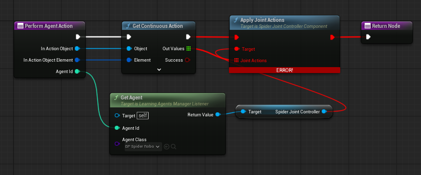
이제는 BP_SpiderInteractor에서 Gather Agent Observation 을 구현해야 한다. 즉 로봇 상태를 실제 Observation으로 넣는 단계라고 할 수 있다.
flowchart TD
    A[BP_SpiderInteractor] --> B[Gather Agent Observation]
    B --> C[Agent ID로 BP_SpiderRobot 찾기]
    C --> D[GetBodyObservationValues]
    C --> E[SpiderJointController.GetJointObservationValues]
    D --> F[Body Observation]
    E --> G[Joint Observation]
    F --> H[Learning Agents Observation]
    G --> H
4.1. [BP]Gather Agent Observation 오버라이딩#
이 함수의 목적은 현재 Agent, 즉
BP_SpiderRobot의 상태를 읽어서 Policy가 볼 수 있는 Observation 값으로 채우는 것이다 .강화학습 루프에는 크게 두 방향이 있는데 크게
- 학습기 → 로봇
flowchart LR A[Policy / 학습기] --> B[Action 24개 출력] B --> C[BP_SpiderInteractor] C --> D[SpiderJointController.ApplyJointActions] D --> E[24개 관절 목표 회전 변경] E --> F[로봇이 움직임]- 학습기가 이 관절을 이렇게 움직여라 명령을 내리고, 로봇이 명령대로 움직이는 역할
- 로봇 → 학습기
flowchart LR A[로봇 현재 상태] --> B[BP_SpiderInteractor] B --> C[Gather Agent Observation] C --> D[Observation 값 구성] D --> E[Policy / 학습기]- 로봇이 지금 어떤 상태인지 학습기에게 알려주는 역할
이 있다. 1번 학습기 → 로봇 방향은 이미 Action 쪽에 구현을 완료했으니, 여기서부터는 반대 방향을 구성하면 된다.
1. Get Agent 노드 만들기 및 연결#
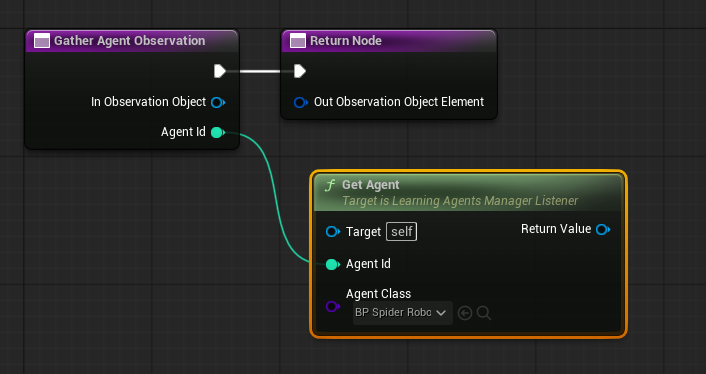
- Gather Agent Observations/Agent Id → Get Agent 노드 연결
- Get Agent/Agent Class → BP_SpiderRobot
2. Body Oservation 읽기#
- 실제 로봇 객체를 등록했으니, 그 로봇의 몸체 상태를 읽어야 한다.
- 전에 만든 BP_SpierRobot 안에 만든 함수(GetBodyObservationValues)를 다시 보면, 이런 식으로 몸체 상태를 9개의 값으로 반환한다
odyRoll
BodyPitch
BodyYaw
BodyHeight
ForwardVelocity
RightVelocity
AngularVelocityX
AngularVelocityY
AngularVelocityZ
이 값들은 Policy가 로봇 상태를 이해하기 위한 기본 정보들로 정의했기 때문에 이 값을 Agent로 등록한 객체에게서 출력을 받아야 한다. 우리가 생성한 해당 함수로 몸체 상태를 출력하게 하
Get Agent/Return Value 출력핀 드래그 →Get Body Observation Values노드 생성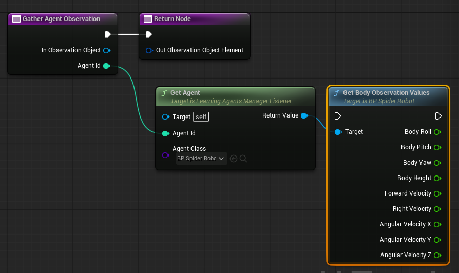
여기까지 하면 이제 Agent에 해당하는 실제 로봇을 찾고, 그 로봇의 몸체 상태 9개를 읽는 데 성공한 것이다.
4.2. [BP]관절 상태 읽기#
Policy가 다음 Action을 잘 만들려면 몸체의 상태뿐만이 아니라, 현재 각 관절이 어떤 상태인지도 알아야 한다.
앞다리가 이미 많이 접혀 있는가?
뒷다리가 펴져 있는가?
현재 Action이 어느 관절 목표값을 만들고 있는가?
그래서
SpiderJointController에서 관절 상태 배열을 읽어서 전달해야 한다.
1. SpiderJointController가져오기 및 확인#
Get Agent/Return Value → Spider Joint Controller 노드 연결
Spider Joint Controller →
Get Joint Observation Values호출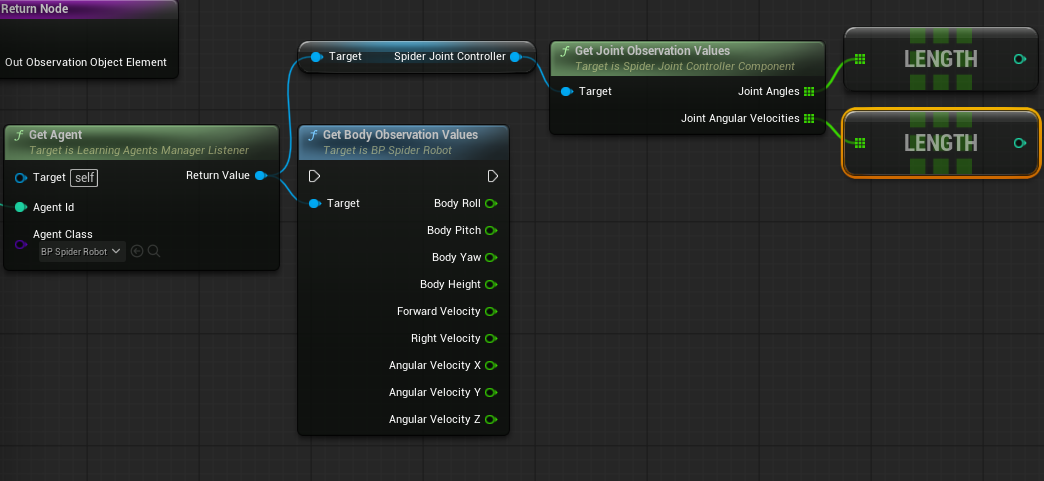
출력 확인 : Print String 2개 만들기
- 빈 공간 우클릭 → Print String을 2개 생성
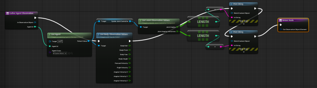
Print String 1 = Joint Angles 배열 길이 확인 Print String 2 = Joint Angular Velocities 배열 길이 확인- Length 값을 Print String에 연결
- 실행선 연결
지금
Gather Agent Observation에서 바로Return Node로 가는 흰색 실행선을해당 형식으로 변경
Gather Agent Observation 실행 핀
→ Get Body Observation Values 실행 핀
→ Print String 1
→ Print String 2
→ Return Node
Get Body Observation Values함수는 파란색 함수 노드라서 실행선이 있어야 실제로 호출되는 함수이기 때문이다.최종 테스트 출력 형태
BP가 또 초기화해서 관절 설정이 누락되었을 수도 있으니, BP_SpiderRobot→SpiderJointController의 디테일→SpiderJoint으로 가서, Joint Config Data 확인

4.3. [BP]Specify Agent Observation 오버라이딩#
- 지금까지 한작업이 Agent에서 값들을 가져오는 단계라면,
도식화
flowchart LR
    A[BP_SpiderRobot] --> B[GetBodyObservationValues]
    C[SpiderJointController] --> D[GetJointObservationValues]
    D --> E[JointAngles Length 확인]
D --> F[JointVelocities Length 확인]- 이제는 읽은 값들을 읽은 값을 실제 Learning Agents Observation Object에 넣는 작업을 수행해야 한다
도식화
flowchart LR
    A[Body 값 9개] --> D[Observation Vector]
    B[JointAngles 24개] --> D
    C[JointVelocities 24개] --> D
    D --> E[Policy 입력]
Learning Agents에서는 보통 Observation을 그냥 Gather에 막 넣는 게 아니라, 먼저 Observation 구조를 선언을 하고 다음에 실제 값을 채워넣으라고 명시되어 있다.
즉,
Specify Agent Observation은 그릇 만들기Gather Agent Observation은 그 그릇에 실제 값 담기
로 구성을 해야한다.
1. Specify Continuous Observation 추가#
- 빈 공간 우클릭 → 노드 추가(Specify Continuous Observation)
- 우리는
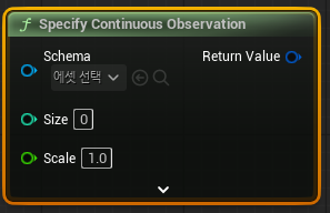
이 Agent는 매 스텝마다 Float 값 여러 개로 구성된 Observation을 받을 것이다.
그 개수는 현재 57개다.
이 Observation의 형태를 미리 선언을 해줘야 한다.
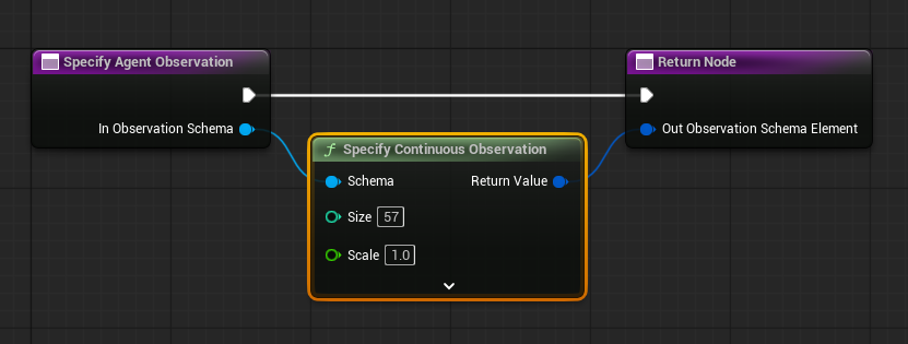
Specify Continuous Observation/Size = 57
Specify Agent Observation노드/In Observation Schema → Specify Continuous Observation /Schema 연결Specify Continuous Observation/Return Value → Return Node / Out Observation Schema Element 연결완성 구조
2. BP_SpiderRobot에서 최종 Observation 배열 생성#
- Gather Agent Observation에서 직접 Body 값과 Joint 값을 조립하지 않는다.
- BP_SpiderInteractor는 Learning Agents와 로봇을 연결하는 중계자 역할만 담당하고, 실제 Observation 배열 조립은
BP_SpiderRobot에서 수행하도록해야 Interactor 클래스의 역할이 분리가 된다
구조 요약
flowchart TD
    A[GetObservationValues] --> B[GetBodyObservationValues 호출]
    A --> C[SpiderJointController]
    C --> D[Get Joint Observation Values]

    B --> E[Body 값 9개]
    D --> F[JointAngles 배열]
    D --> G[JointAngularVelocities 배열]

    E --> H[ObservationValues 배열 생성]
    F --> H
    G --> H
    H --> I[Return]
1) 최종 Obaservation 종합 함수 생성 및 필요 변수 나열
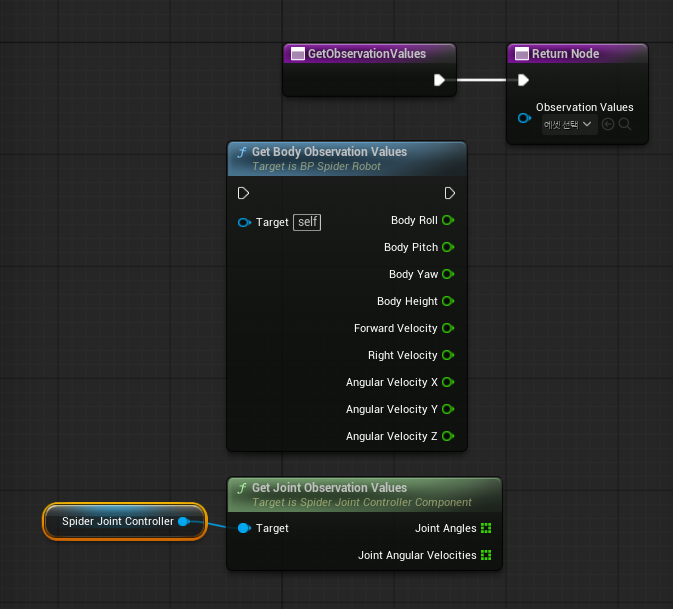
따라서 BP_SpiderRobot에 다음 함수를 추가해보자
GetObservationValues : Float Array
용도
Body Observation 9개
JointAngles 24개
JointAngularVelocities 24개
수집 후 하나의 배열로 반
출력 추가 (ObservationValues : Float Array)
기존 Body 함수 호출 (Get Body Observation Values)
C++ 함수에서 만든 Spider Joint Controller/Get Joint Observation Values 함수 호출
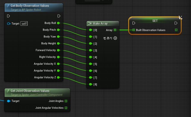
2) 임시 배열 생성 및 통합 Observation 배열 조립 - Body 배열
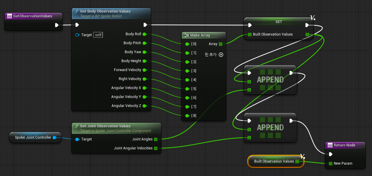
빈 공간 우클릭 → Make Array 생성 →핀을 9개로 늘리고 아래 순서대로 연결
[0] Body Roll
[1] Body Pitch
[2] Body Yaw
[3] Body Height
[4] Forward Velocity
[5] Right Velocity
[6] Angular Velocity X
[7] Angular Velocity Y
[8] Angular Velocity Z
MakeArray/Array → Prompt to Local Value 선택 후, 로컬변수 이름 변경(BuiltObservationValues)
관절 24개를 하나하나 펼치지 않는 게 핵심이야.
2. Make Array 결과를 BuiltObservationValues에 Set#
BuiltObservationValues 로컬 변수를 그래프로 드래그해서:
Set BuiltObservationValues선택.
그리고 연결:
Make Array의 Array 출력
→ Set BuiltObservationValues의 배열 입력
실행선은:
GetObservationValues 시작
→ GetBodyObservationValues
→ Set BuiltObservationValues
의미는 이거야.
BuiltObservationValues = [BodyRoll, BodyPitch, BodyYaw, BodyHeight, ForwardVelocity, RightVelocity, AngularVelocityX, AngularVelocityY, AngularVelocityZ]3. JointAngles 배열 붙이기#
BuiltObservationValues를 Get으로 그래프에 꺼내.
그 배열 핀에서 드래그해서:
Append Array선택.
연결:
Target Array = BuiltObservationValues
Source Array / New Items = Joint Angles
실행선:
Set BuiltObservationValues
→ Append Array JointAngles
의미는:
BuiltObservationValues 뒤에 JointAngles 배열 24개를 통째로 붙인다.4. JointAngularVelocities 배열 붙이기#
Append Array를 하나 더 만든다.
연결:
Target Array = BuiltObservationValues
Source Array / New Items = Joint Angular Velocities
실행선:
Append Array JointAngles
→ Append Array JointAngularVelocities
이제 배열 길이는:
9 + 24 + 24 = 575. Return Node에 연결#
마지막으로 BuiltObservationValues를 Get으로 꺼내서 Return Node의 출력에 연결해.
BuiltObservationValues
→ Return Node.ObservationValues
실행선은 최종적으로:
GetObservationValues
→ GetBodyObservationValues
→ Set BuiltObservationValues
→ Append Array JointAngles
→ Append Array JointAngularVelocities
→ Return Node
구조로 보면 이렇게야.
먼저 BuiltObservationValues 로컬 변수 만들고, Make Array에 Body 9개 연결한 화면까지
3) 임시 배열 생성 및 통합 Observation 배열 조립 - 관절 배열
Set BuiltObservationValues노드 오른쪽의 초록 격자 핀 또는 왼쪽 변수 목록의BuiltObservationValues에서 드래그해서 Get BuiltObservationValues를 하나 꺼낸 후, 그 배열 핀에서 드래그해서 검색(Append Array) 후 노드 추가- 두 번째
Append Array로 JointAngularVelocities 붙이기
최종 흐름#
관절 24개를 하나하나 펼치지 않는 게 핵심이야.
2. Make Array 결과를 BuiltObservationValues에 Set#
BuiltObservationValues 로컬 변수를 그래프로 드래그해서:
Set BuiltObservationValues선택.
그리고 연결:
Make Array의 Array 출력
→ Set BuiltObservationValues의 배열 입력
실행선은:
GetObservationValues 시작
→ GetBodyObservationValues
→ Set BuiltObservationValues
의미는 이거야.
BuiltObservationValues = [BodyRoll, BodyPitch, BodyYaw, BodyHeight, ForwardVelocity, RightVelocity, AngularVelocityX, AngularVelocityY, AngularVelocityZ]3. JointAngles 배열 붙이기#
BuiltObservationValues를 Get으로 그래프에 꺼내.
그 배열 핀에서 드래그해서:
Append Array선택.
연결:
Target Array = BuiltObservationValues
Source Array / New Items = Joint Angles
실행선:
Set BuiltObservationValues
→ Append Array JointAngles
의미는:
BuiltObservationValues 뒤에 JointAngles 배열 24개를 통째로 붙인다.4. JointAngularVelocities 배열 붙이기#
Append Array를 하나 더 만든다.
연결:
Target Array = BuiltObservationValues
Source Array / New Items = Joint Angular Velocities
실행선:
Append Array JointAngles
→ Append Array JointAngularVelocities
이제 배열 길이는:
9 + 24 + 24 = 575. Return Node에 연결#
마지막으로 BuiltObservationValues를 Get으로 꺼내서 Return Node의 출력에 연결해.
BuiltObservationValues
→ Return Node.ObservationValues
실행선은 최종적으로:
GetObservationValues
→ GetBodyObservationValues
→ Set BuiltObservationValues
→ Append Array JointAngles
→ Append Array JointAngularVelocities
→ Return Node
구조로 보면 이렇게야.
먼저 BuiltObservationValues 로컬 변수 만들고, Make Array에 Body 9개 연결한 화면까지
4) 리턴 노드 구조 수정
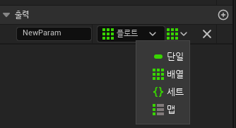
Return Node → 디테일 → 출력에서 플로트 / 배열 선택
2번째 Append 실행 핀 → Return Node, Get Build Observation Values → Return Node
최종 구조
이제 실제로 로봇 블루포인트에 연결을 해서 테스트를 해보자
BP)SpiderRobot으로 들어가서 이렇게 노드를 연결하고 컴파일 실행 후, 로그를 확인

LogAudioMixer: Deinitializing Audio Bus Subsystem for audio device with ID 10
LogAudioMixer: Display: FMixerPlatformXAudio2::StopAudioStream() called. InstanceID=10, StreamState=4
LogAudioMixer: Display: FMixerPlatformXAudio2::StopAudioStream() called. InstanceID=10, StreamState=2
LogUObjectHash: Compacting FUObjectHashTables data took   0.77ms
LogPlayLevel: Display: Destroying online subsystem :Context_16
정상적으로 Observation을 할 값들이 모두 출력된 걸 확인할 수 있다.
#
4.4. [BP]로봇 Observation 값을 Learning Agents Observation으로 전달#
이제 BP_SpiderRobot에서 생성한 Observation 배열을 BP_SpiderInteractor가 받아서, Learning Agents의 Observation 객체에 실제 입력값으로 전달하는 단계이다.
즉, 지금까지 만든 몸체 상태, 관절 상태, 관절 각속도 값이 Policy가 입력으로 사용하는 Observation Vector가 되도록 연결하는 것이 주요 목표이다
flowchart LR
    A[BP_SpiderRobot] --> B[GetObservationValues]
    B --> C[ObservationValues Float Array]
    C --> D[BP_SpiderInteractor]
    D --> E[Gather Agent Observation]
    E --> F[Learning Agents Observation]
    F --> G[Policy 입력]
Gather Agent Observation 수정#
먼저 BP_SpiderInteractor 의 Gather Agent Observation 함수로 이동
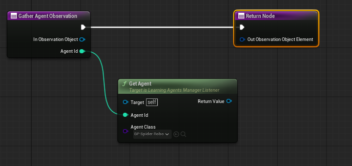
Get Agent/Return Value → Get Observation Values 노드 연결해서 로봇의 상태값을 꺼내도록 하자
실행 흐름을 Gather → Get Observation Values → Return 노드로 정리
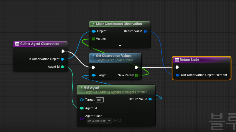
Gather Agent Observation노드에 있는 파란 핀→Make Continuous Observation노드 생성(Make Continuous Observation | Unreal Engine 5.7 Documentation | Epic Developer Community)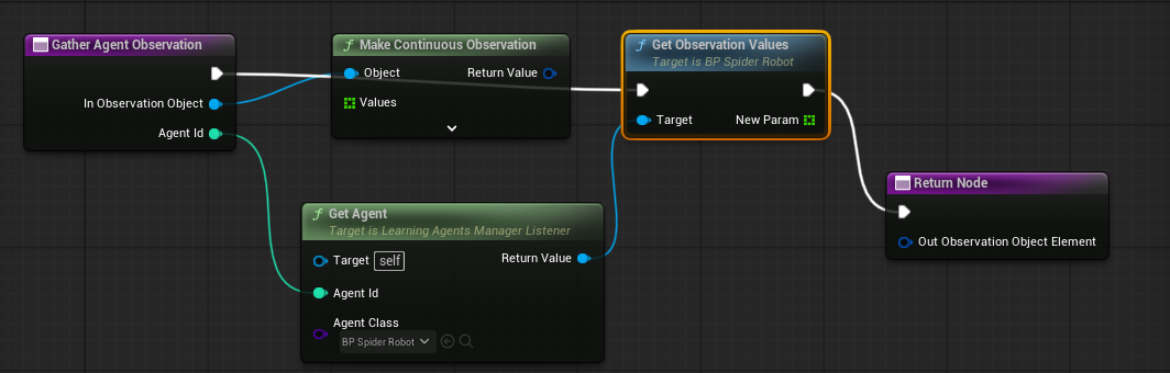
- 이 노드는 새로운 연속 Observation을 만들어서 객체에서 받은 값(57개 배열)을 Learning Agent가 입력받는 Observation Element로 래핑해서 전달하는 역할을 수행한다.
Get Observation Values의 배열 출력을Make Continuous Observation에 연결해서 우리가 로봇에서 뽑은 float Array 값을 Continuous Observation 형식으로 감싼다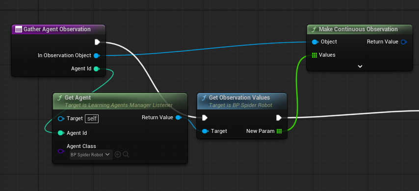
Make Continuous Observation/Return Value → Return Node/Out Observation Object Element 연결컴파일 후 실행 오류 체크
최종 구조
flowchart TD
    A[Gather Agent Observation 호출] --> B[Get Observation Values 실행]
    B --> C[Return Node 실행]

    D[Agent Id] --> E[Get Agent]
    E --> F[BP_SpiderRobot 참조]
    F --> B

    G[In Observation Object] --> H[Make Continuous Observation]
    B --> I[ObservationValues 배열]
    I --> H
    H --> J[Out Observation Object Element]